Introduction
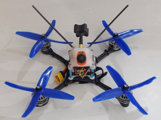
I’m building a Shendrones Krieger (the DTF200 model for 5″ props) and thought I would document the build as I go, for my own future reference and in case anyone else is interested. The main components are:
My objective is to build a competitive racing and freestyle quad, which can carry an HD camera, for a reasonable cost.
In this build log I won’t cover the basic assembly of the Krieger frame, since this is covered well in the Krieger Setup Guide. The only thing I did differently is that I assembled the flight controller stack onto the base plates and arms before adding the pod, since this gave me much better access to the electronics for soldering and routing cables.
Building the Arms
For this build I am using Dys XM20A ESCs and rcINpower GT2205-2300 motors. One of the reason I chose these particular ESCs is because they are just small enough to fit entirely on the Krieger’s diminutive arms, without having to extend over the body plate that the arms attach to. This should make for a neater build, as well as facilitating arm replacement in the field if necessary. This is how I built each of the arms.
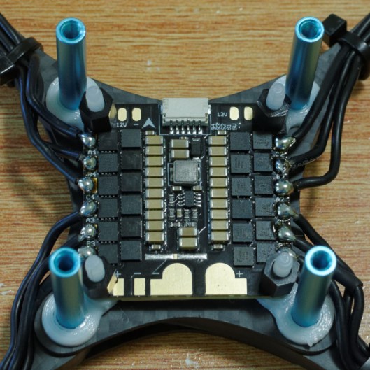
1. Remove the heatshrink from the ESC
Peel off the sticker then with a small pair of side cutters, nibble across the side of the ESC that the sticker was on. There’s a fairly clear “channel” between the top 4 FETs and the bottom 2 FETs and then between the 3 capacitors at the bottom of the board next to the positive lead and the regulator (orientation as per the image below) that allows you to cut without bumping into any components. Take it slow and gentle, just a mm or two at a time, to avoid stressing the components on the board.

I have the “Version 2” ESCs, which means they had wires attached for the motors, so I removed these wires and cleaned up the pads with some solder braid. The “Version 1” ESCs, which don’t have wires attached, would be simpler. Note that the current generation of the XM20A does not have a heatsink, which is one less thing to worry about.
2. Attach the ESC to the arm using foam tape
While this sounds crude, the double-sided tape provides some vibration damping for the ESC while insulating it from the arm. I used 3M 4026 double coated urethane foam tape which is 1.6mm thick and does not conduct. I bought the 25mm (1″) wide tape. This is almost exactly the length of the ESC (excluding the tabs where the motor wires connect), so you can just cut a 15mm piece from the tape, which will then fit under the ESC (excluding tabs) with about 0.5mm excess on all sides. Don’t stick the tape under the protruding motor tabs because they will get hot when soldering the motor wires on, and because you may need the space between the tabs when soldering the wires.
In order to ensure that you position the ESC correctly, attach the arm to the Krieger (I use standard M3 bolts, not Nylocks for this, both to save time and because its not advisable to keep screwing and unscrewing the Nylocks as they will lose their vibration resistance). Place the ESC as close to the body plate as possible while ensuring that the power and signal leads cannot short against the body plate!

3. Solder the motor wires to the ESC
Bolt the motor to the arm (without any thread-locker since you will need to remove it to strip the wires). Two bolts will do, but ensure it is properly positioned. Cut the motor wires so they just reach the end of the pads (literally only about 5mm of lead remaining on the motor). Remove the motor and strip 2mm or so at the end of each wire (fortunately the GT2205 has silicone wire at this point so you don’t have to scrape enamel off magnet wire). The replace the motor on the arm (this time you can use thread-locker) and solder the motor leads to the ESC pads (solder to the top of the pads to prevent the wires from shorting against the arm). I find it easiest to solder the middle lead first, since once the outside leads are soldered they may end up touching the middle pad, and even though its silicone wire I don’t want to test the melting point of the insulation.
I’ve soldered the leads in order, without any cross-overs, on all arms. I’ll set the motor direction using BLHeliSuite (which allows one to reverse the direction of a BLHeli ESC) rather than having to do crossovers in the minute space available.

4. Heatshrink over the ESC and arm
Cut a length of 19mm (3/4″) diameter heatshrink sufficient to cover the ESC (including the solder joints on the tabs connecting the motor wires). Remove the arm from the base plates, slip the heatshrink over, reattach the arm (using the Nylocks this time) and shrink it on. This will hold the ESC firmly against the foam tape and protect it from the elements. However, I suggest that you first confirm whether the ESC power leads are long enough to reach your PDB before heatshrinking them. The XM20As have short power leads, so I had to remove the power leads from two of the ESCs and replace them with longer wires. I also recommend testing the motors before you heatshrink the ESCs!

Finally, a cable tie over the arm and ESC wires near the body of the quad will provide strain relief and stop any slightly long wires from being caught by the props. (You can see this in the picture of the finished Krieger at the top of the post).
Installing the Receiver – Take 1
Note:- before you do this, read the next section, “Postscript: Installing the Receiver – Take 2”.
My radio is a Futaba 6K, which uses the R3006SB s-bus receiver. I knew that installing the R3006SB in the Krieger would not be simple. I had confirmed with Andy Shen (designer of the Krieger) that the pod would be big enough, but had no real idea how I would actually mount it – in the absence of 3D CAD models, I find it easiest to do this once I have the physical objects to play with.
The Krieger has a recess at the bottom of the pod which is intended for mounting the receiver, but it is about 0.5mm too narrow and about 1.5mm too short to fit the R3006SB.I decided it would be possible to remove 0.75mm of carbon from the front and back of the recess without weakening it horribly. However it was not possible to remove material from the sides since it is the flight controller stack mounting holes that obstruct the receiver, and there is not enough carbon fibre around the mounting holes for me to consider it safe to remove any!
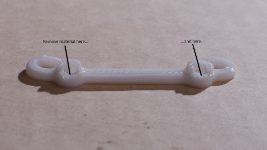
So what I did was file about 0.25mm of plastic off the left and right sides of the R3006SB enclosure. It’s only necessary to file away material at the front and back of the receiver, since this is where the flight controller mounting points prevent the receiver from fitting into the recess. It took longer than expected (the plastic is surprisingly strong), but eventually I was able to achieve a friction fit of the receiver between the mounting points. Then it was simply a matter of filing about 0.75mm of carbon from the front and back of the recess in the top body plate of the Krieger (sorry Andy), and I was able to fit the receiver into the recess. Although the receiver is held in by friction, the battery strap also goes around it.

The final challenge was to route the antennas of the recess. I cut a notch in the top of the 4mm carbon fibre spacer that sits between the top and bottom plates, and routed the antennas through that (see picture below). I also discovered to my annoyance that I had to create a couple of “V” shaped cutouts in the top plate to allow the antennas to feed into the notch. I hope I haven’t weakened the Krieger too much! Only time (and crashes) will tell….

Installing the Receiver – Take 2
So in my first week of flying the Krieger, I learned something abut quads with under-slung batteries: they break battery straps. Often. (Especially when you use rubbish silicone straps – these ones are much better and are the perfect size for a 1300 4S lipo). Which makes my initial approach to installing the receiver problematic, because to replace the battery strap you have to remove the pod, and then spend ages fiddling to get the new battery strap through the slot, up over the receiver, and back through the other slot. It’s doable (I’ve done it twice!), but not something you want to be having to do between heats.
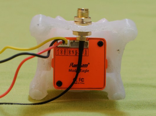
So instead I have mounted the receiver using strips of foam tape placed on either side of the receiver. I used three strips of 1.6mm tape on top of each other on the side where the antennas exit the enclosure, and two pieces underneath the side where the servo connectors are. This is sufficient to allow the antennas to exit the receiver above the level of the frame, without raising the level of the connectors by too much. This leaves a gap under the receiver, which allows the battery strap to route as Andy intended it to, horizontally over the bottom plate rather than up and around the receiver. This makes it relatively easy to replace straps, without having to dismantle anything.

The foam tape goes here…
The problem of course is that the servo connector is now 3.2mm higher, and a standard servo plug (for the S-Bus connection) would interfere with the bottom of the OSD PCB. To solve this, I made myself a 90 degree servo connector by removing the pins, cutting the top off, reinserting the pins, bending them 90 degrees and then heat-shrinking both the individual wires and over the entire assembly, with large diameter shrink over the bend, and smaller diameter shrink forming a “boot” over the wires for strain relief.

The completed installation fits into the same overall stack height as the original one, but without having to modify the middle and bottom body plates, since the receiver antennas now come out above the level of the top plate. No frame modification required!
Flight Controller Stack
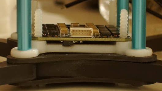
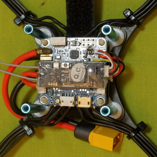
The stack consists of the RROSD Pro PDB/OSD and the Foxeer F303 flight controller. I built it up using M3 x 30mm bolts. I used steel bolts because that’s all that was available locally, but I may eventually replace them with Nylon to save a few grams. I cut lengths of 4mm silicone rubber tubing (bought from an aquarium supply shop) to use as spacers. The idea is that the flexible, compressible silicone rubber spacers will serve as vibration dampers for the stack, hopefully eliminating some of the high frequency vibration. There are silicone spacers below the PDB/OSD, between it and the flight controller, and between the flight controller and the nuts that hold the stack together. These are only tightened sufficiently to compress the silicone a bit, and are secured with copious amounts of thread locker! Note that I did not put nuts below the stack to hold the bolts against the body plate, since this would defeat the purpose of allowing the stack some “sway” to dampen vibrations.
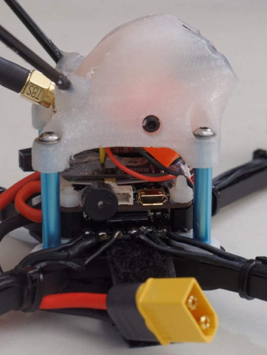
I mounted the RROSD so the video connections were at the front, the battery and camera connections on the back, and ESC power connections on the right hand side. It would have been easier if the RROSD had ESC power pads on both the left and right side of the PCB! The flight controller is mounted with the USB port facing backwards for easy access, which conveniently puts the motor control outputs on the left, so they don’t conflict with the ESC power leads which are on the other side of the stack. All cables are routed in at the front or back of the stack, between the side plates of the pod. Nothing routes through the cutouts in the side plates, so that the pod can be removed if necessary to give access to the stack.
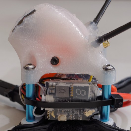
Here is a view from the back, showing the structure of the stack. The OSD/PDB has to be mounted quite high to clear the servo connector in the receiver.

FPV Camera, VTX and Lost Model Buzzer
After having used an HS1177 on my ZMR250, I decided to try the new Foxeer XAT1200M 16:9 aspect ratio camera on the Krieger. It only costs $2 more than the HS1177, and I thought it might be nice to have a correctly proportioned display in my 16:9 goggles. In any case I will be building a Liberty Ducted Quad for my son soon, so if I don’t like the XAT1200M it will find a home in the Liberty…. The XAT1200M has the same form factor as the HS1177 so mounting it was no problem, using the designer approved hot glue method!
The VTX is a Foxeer TM25 Switcher, which can be switched (using the push button) between 25, 200 and 600mW. This will be really useful because the local competitions limit VTX output to 300mW maximum for racing, while it can be nice to have a bit more power for proximity flying in wooded areas. The VTX just fits in the frame, and a hole is provided for the SMA antenna connector. While the antenna and a washer can hold the VTX in position, I was a bit leery of relying on the antenna connector as the sole mechanical support. After trying in vain to come up with a better solution, I eventually stuck a 25mm x 7mm strip of 1.6mm double-sided foam tape on the top of the flight controller and rotated the VTX so it was roughly parallel to the sloped to of the pod, with the side stuck to the foam tape on the top of the flight controller PCB. It’s not an ideal solution, and I shall have to be very careful if I need to swap out the TX to ensure I don’t rip and components off the FC PCB. However it’s better, in my opinion, than supporting the VTX solely by its SMA connector.
Postscript: the double sided tape does not work well to secure the VTX, as it tends to come unstuck. I’ve now switched to using a cable tie that goes around the VTX and the rear standoff. Note that Foxeer have also changed the SMA connector location of the TM25 Switcher – the one I used in this build had the connector offset to one side, while the latest version has the connector mounted centrally.
I used hot glue to stick the lost model buzzer on the inside of the right hand vertical side plate, over the hole that is there for a cable tie to secure the antenna if it is mounted on that side (my antenna is mounted on the other side). The hole provides an outlet for the sound. You can see the piezo buzzer mounted in the smaller hole near the centre of the image below.

I bent the buzzer pins flat against its body after soldering to prevent them from fouling the FPV camera when it is set to high angles. While I cut all other wires to length, I suggest using quite long wires to connect the buzzer, so that you can remove the pod and set it aside for access to the flight controller stack without having to de-solder the buzzer. These wires don’t carry large currents or high frequencies, so the only penalty is the (minimal) additional weight.
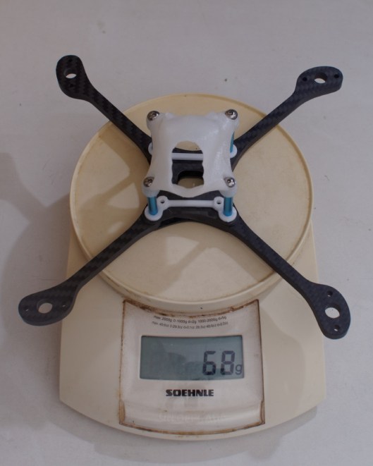
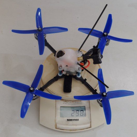
Conclusion
The assembly and integration testing is now complete, although I still need to configure the flight controller and ESCs (fortunately BLHeli pass-thorough does work, so I won’t have to rewire the ESCs!). It’s taken me a rainy weekend (between family responsibilities) but it’s been a whole lot of fun. The completed Krieger weighs 350g without battery (please excuse the scale!) and has a flight weight of 504g with a 1300mAh 4S battery. She’s a real jewel of a quad – compact but solid, a study in mechanical integrity and precision.