
Pic: FPV HQ
Note: When flashing Cleanflight/Betaflight to the Foxeer F303, use the SP Racing F3 target and set the Baud Rate to 256,000 bps.
Introduction
The Foxeer F303 (not to be confused with the similar-but-different X-Racer F303) is a new F3 flight controller (released June 2016). The current price (at surveilzone.com) is US$ 19.99, making it one of the cheapest F3 controllers on the market, so I thought it would be worth trying for my new Shendrones Krieger build. Since I couldn’t find any independent reviews, I thought I would write one myself.
The review unit was purchased using my own funds. Neither Foxeer nor Surveilzone are aware that I am writing a review, and I am not receiving any consideration from either company or any benefit from advertisements.
Overview
The F303 is essentially a functional equivalent of the original X-Racer F303. It has
- 8 PWM inputs;
- S-Bus input, with built in inverter;
- Spektrum Satellite receiver input with 3.3V regulator;
- 8 ESC outputs;
- Two UARTs (excluding the dedicated S-Bus input);
- Buzzer output.
- Micro-USB connector
- MPU6050 gyro/accelerometer but no magnetometer (compass) or barometer. This uses I2C so the max gyro update rate is about 2 kHz.
- 8 MB flash for blackbox logging. This is the same as the original SP Racing F3 board, but only half of the amount the X-Racer F303 has.
- SiLabs CP2102 hardware USB to serial bridge (not a software virtual com port implementation). This means the Cleanflight/Betaflight configurator does not need to be reconnected after the flight controller is rebooted, for example on exiting from command prompt mode, because the CP2102 can remain connected to the PC while the CPU reboots.
Like the original X-Racer F303, it does not have a VBAT input and requires a regulated 5V supply, so you can’t power it directly from the flight battery. This is not a problem for me, as I will be using the RedRotor RROSD Pro PDB/OSD, which will provide 5V for the F303 and generate an on-screen display with battery voltage and current.
While functionally equivalent to the X-Racer F303, the Foxeer F303 is not simply a clone. It uses some different components and the PCB layout is quite different although most of the I/Os are in the same place. The exceptions are:
- The S-Bus connector is moved to the other side of the PCB, next to the ESC outputs.
- The Spektrum Satellite port is through-hole connectors where the S-Bus input is on the X-Racer F303.
- The Buzzer output is plated through-holes, not pads (an improvement).
- The boot button is replaced by through-holes. While a push button is more convenient, the through-holes work better than pads – simply shape a short piece of solid hookup wire into a “U” shape and you can insert it into the adjacent holes; the springiness of the wire will hold it in place while you connect the USB to boot in DFU mode.
- The USB connector is positioned in the centre of the side of the PCB, as opposed to off-centre on the X-Racer F303; and the boot through holes have been moved off-centre to where the X-Racer F303 boot button is.
All connections on the Foxeer F303 use plated through-holes. I like this because the through-holes provide a degree of mechanical strain relief when the wires approach the PCB from the side and then turn 90 degrees through the hole. Surface mount pads, on the other hand, do not provide any strain relief – the solder joint takes the full force of any pressure on the wire – and are in my opinion more likely to fail when exposed to shock unless externally strain relieved.
The board came with a set of male pin headers – right angle for 8 PWM inputs and 4 ESC outputs, and enough straight connectors for the two UARTs and the buzzer, which you can solder in if you like. I prefer to direct solder the wires for better reliability and to conserve space.
Build Quality
The PCB measures 35 x 35mm and is 1.6mm thick.The mounting hole centres are on the standard 30.5 x 30.5mm pattern although they have been made slightly elliptical, presumably to allow some tolerance for the actual mounting pillar separation. This means that the holes extend to within about 0.6mm of the PCB edge; I would have preferred a little more material there for better impact resistance. The weight according to my kitchen scale is 6g (without headers).
The PCB appears to be a 4-layer FR4 board. It has black solder mask with white silkscreen, and components are mounted on both sides. All components are surface mount and machine placed. All through holes are plated; there are no solder splashes or cut and wire modifications; the silkscreen is clear and legible; and all I/O is clearly labelled (although the buzzer labels are on the back of the board). Layout seems reasonable, although the crystal/resonator and possibly some of the decoupling caps are mounted on the bottom of the board, which is not how I would have done it. Tracks are generally short and 90-degree bends are chamfered. The S-bus signal track is somewhat longer than others (presumably due to the location of the S-Bus connections), but given the low data rate this is nothing to be concerned about. The board is not conformally coated, although this is not expected in a consumer grade product.
Overall I consider the build quality to be very good.
Power Requirement
There is no step-down regulator so you need to supply 5V. It draws 57mA (not armed, no receiver connected, ESCs connected, beeper off). With a Futaba R3008SB receiver connected and drawing power from it, mine draws about 85mA peak.
Betaflight
The F303 came preloaded with Cleanflight 1.12.0. Since I decided to use Betaflight for this build, I used the firmware updater on the Betaflight configurator to flash Betaflight 2.9.0. This was straightforward; it (like the original X-Racer F303) uses the SP Racing F3 target and the only “gotcha” is that you must remember to manually set the baud rate to 256000 bps or it won’t be able to communicate with the boot loader. I did not need to use the boot pins to force DFU mode or load any special drivers.
One strangeness I noticed is that even though the printed arrow on the PCB points 90 degrees left of the direction of flight on my installation, I had to set the Betaflight GYRO Alignment and and ACCEL Alignment parameters to “CW 180” to obtain correct readings.
S-Bus and UARTs
The F303 works with Futaba S-Bus. Like all F3 boards I am aware of, an external inverter is not required. One thing that caught me out during configuration is the UART port. I connected my R3006SB receiver to the SBUS input on the F303. Since there are two UART connectors on the F303 PCB, labelled “UART 1” and “UART 3”, I assumed that the S-Bus would be on UART 2. However when I selected UART 2 in BetaFlight, the receiver was not connected. Eventually I found the S-Bus input on on UART 3.
Of course this raises the question of what happens to signals on the UART 3 port. In order to determine this, I connected my S-Bus receiver to UART 3 on the F303, and Betaflight could still see the receiver without having to change the configuration. So the S-Bus port and UART 3 are effectively connected in parallel, and can’t be used simultaneously. And since the F303 runs the SP Racing F3 Cleanflight/Betaflight targets, I presume (but have not confirmed) that UART 1 is shared with the USB, as is the case on the SP Racing F3. This makes the lack of access to UART 2 all the more questionable.
BLHeli and Lost Model Buzzer
BLHeli pass-through works perfectly. I can see all the ESCs, flash them with new firmware, and update parameters. One-shot 125 also works fine, and so does the lost model buzzer (unlike some of the early SP Racing F3 clones, where the buzzer did not work).
In Flight
It flies fine. While this is my first F3 flight controller, so I can’t make any direct comparisons, I expect it flies just like any other F3 flight controller with an MPU6050 gyro.
Conclusion
It’s cheap, the build quality is good, and it works well. Unfortunately there are only two UART ports – UART 1 and UART 3, with UART 1 (probably) being shared with the USB and UART 3 also being used for S-Bus. So if you want a serial receiver, OpenLog logger and a serial-connected OSD, then the F303 is not the right choice. The lack of a VBAT pin will also be an issue if you plan to use a Minim OSD or similar, or want to use Betaflight PID scaling with battery voltage. However for simpler configurations, it is an excellent choice.

Nice review as I could not find much information out there on the fc in general. Thanks for the write up. I use it with cleanflight and RROSD.
LikeLike
hello and thanks for review , I just buy f303 and don’t have any experience , i build my own motor driver but have no idea , how to connect it to my foxeer because i don’t know which pin is for motor or PWM , GND and 5v , have you schematic of any circuit ??
or can you help me by wiring ??
LikeLike
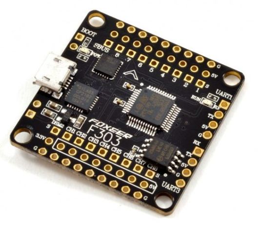
If you look at the picture of the F303 at the top of the blog post, the plated holes at the top labelled “1” to “8” are the PWM output. The square pad right next to the number is the PWM signal, which is labelled “S” on the far right hand side (in the photo orientation). The middle, round holes are +5V (ESC positive supply), and are labelled “5V” on the right side. The holes closest to the edge, labelled “G” are ground (ESC negative supply). The holes labelled “CH1” to “CH8” at the bottom are the receiver inputs – they are also labelled “S”, “5V” and “G” for Signal, +5V and Ground.
LikeLike
Thanks for your reply.
I have another question , which firmware is proper for foxeer f 303 ?
Spracingf3 or foxeer405 or something else?
LikeLike
SP Racing F3
LikeLike